Construction

Rear View of EV
Approximately 1/2 of the parts will be purchased with the remaining 1/2 machined. These parts will be the fasteners that hold the bearings, the mounting brackets for the electric motor, adjustments to the key and shafts.
Drive Train
The chain drive begins with the mounted motor, bolted just behind the driver seat. The 0.77 in diameter, keyed shaft is attached to the motor. Mated to the motor shaft is the 17 tooth sprocket with the ¼”x ¼“ key. The chain wraps around the 60 tooth driven sprocket with a center distance of 20 inches to the driving sprocket. The driven sprocket is mated with a keyed bushing. The driven shaft goes through the wheel and mates with the sprocket bushing as they share a ¼”x ¼” keyway as well. On both ends of the driven shaft there are ball bearings which are held in place by machined fasteners.
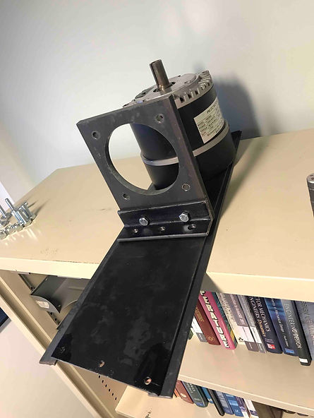
System Mount
The mount assembly connecting the motor and frame is composed of twelve different parts. Bolted with four 1/2”-20, 1-3/8” long bolts, the motor fits snug to the steel motor mount’s 4.5” diameter hole; it is intended for the face with the driving shaft of the motor. The bottom of this mount is flush with an angle iron are held together by two 3/8”-16, 1-1/4” long bolts. The other face of the angle iron has three holes that are bolted with the steel motor mount base plate with three ½”-13, 1-1/4” long hex bolts. The base plate is a quadrilateral with a 23” long size and a 21” short size. Flush with the edges, forming upside down Ls, are the steel motor mount base plates. These will be welded to the mount base plate, which in turn will be bolted with six ¼”-20, 3” in long hex bolts to the EV frame, along the equal, smallest sides of the quadrilateral.
Manufacturing Issues
The most prominent manufacturing issue is working with what is available. The bicycle wheel used for the rear wheel drive is going to have to be mated with the large 60 tooth sprocket. Although there are a couple of methods around this, there is going to have to be additional manufacturing changes to the ordered parts. Another issue is managing to align and retain the ball bearings with a manufactured bracket from the machine shop. Although in theory it all should work, theory does not always match the application.
In manufacturing the motor mount there has been a number of issues. At first, 1/8” thick scrap steel was going to be machined as the motor mount base plate. After consultation however, it was deemed too expensive to machine as such due to ribbing and prior modification of the part. Thus a 2’ x 6” steel slab will be used and machined instead. The L-bracket/angle iron was going to be arguably bent; however ¼” in steel is not easy to bend and thus becoming a manufacturing issue. Instead the angle iron will be purchased as such or a change to at least 1/8” thick steel to bend.