Analysis
Proposed Solution
Teamwork is not the unique solution to the project. For the chain drive, the first step taken was figuring out the requirements; what speed would the vehicle have to achieve? How much will the chain drive weigh? What power will it have to transmit? Under what cost? These were the key requirements under which the design would be modeled after.
Next came conducting research on all types of drivetrains suited for this vehicle. It had to be simple enough for a student to be able to create yet complex enough for it to impose a challenge. It would have to be under a certain budget, $500 in this case, and accessible. There would have to be parts that could be personally manufactured or machined and others that would have to be purchased for the assembly to happen. This narrowed down the search to one viable solution: the chain drive. Not too expensive, efficient, and within the realm of plausibility.
Next came the analyses; starting with one of the given requirements, such as horsepower or input RPM from the motor. Those slowly chained themselves together, solving for one variable in order to calculate another. It is through this chain reaction that the system was calculated and built around the original requirements. The analyses green sheets and descriptions can be found here.
Having done the calculations, next came the drawings and tolerances that came with them. Through Solidworks, these ideas slowly took shape. Tolerances had to be placed and the right fitting had to happen.
Requirements
The EV chain drive has few yet selective requirements. First and most obvious, it has to be able to transfer enough power from the motor to the wheel in order to get the vehicle to move. Numerically however, it must reach a minimum speed of 40 mph and output RPM of at least 750. The overall price must not exceed $500 as a budget requirement. Lastly, the number of teeth for sprockets must fall between 17 and 120, no more or less.
Benchmark
There is another electrical vehicle from previous years that is used as the benchmark for this project. It is similar in design to the current chain drive; it has a higher ratio with a larger than average driven sprocket, a smaller than average motor sprocket, has approximately 20 inches of center distance, and uses chain as-well. The benchmark EV is estimated to have a 1 horsepower motor with an output RPM of 2800. The new motor is being held to the same RPM, although this time with 5 horsepower. The benchmark EV reached a peak speed of 50 mph according to professional sources that have tested that vehicle.
Design Issue
The design project has not gone without any issues. The first issue is the electric motor being used. The colleague in charge of the electrical components of the EV, the batteries which power the motor, has tested the input RPM of the motor to be approximately 2800. The motor itself however is labeled for 4250 RPM. Whether this is a temporary issue or a permanent one will have a significant impact on the chain drive. The motor shaft is where the entire design of the train drive begins. Altering this would mean recalculating a velocity ratio which would alter the remainder of the design. The velocity ratio is another possible design issue. The current velocity ratio of 3.52 is considerably good compared to the recommended VR design limit of 7. Once again, a shift in the input RPM from the motor would significantly affect this. The accessibility to parts, such as a 60 tooth sprocket, usually come at a very large price due to the nature of the part. Lastly, the cost of these specific parts pose a financial problem. Some of the parts can sell for up to $150. As stated before finding a part within an economical umbrella that is not very common can be very difficult.
Calculated Parameters
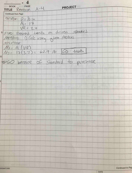
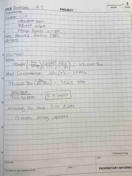
In designing the chain drive, one of the most important design requirements is for the system, as per design guidelines, to have a maximum speed ratio of up to 7.0. Achieving this requirement means meeting a couple other requirements. One of these requirements calls for the motor sprocket to have a minimum of 17 teeth and the driven sprocket a maximum of 120 teeth. The motor sprocket was chosen after calculating the design power and using the table found in the book. The driven sprocket was found using the velocity ratio and motor sprocket teeth number. This larger sprocket has a calculated number of 62 teeth although a 60 tooth sprocket will be used instead for standard compliance. This falls within one of the parameters and requirements, 17 < N < 120, for the chain drive and also means a velocity ratio of 3.52. In order for the system to have a speed of 45 mph with a 20 inch diameter wheel, the calculated output RPM had to be 793 RPM. This presented another challenge because of the difference in gear teeth. The analysis determined the velocity ratio between the calculated output RPM and input RPM to be 3.7. The actual expected output speed, with the 60 tooth sprocket, had to fall between 750 RPM and 800 RPM to roughly maintain the same velocity ratio. The result was a close 793 RPM which meets the requirements and still holds an acceptable velocity ratio.
Electric Motor Mount